Item: Saturn V photo signed by 6 Apollo astronauts
Size: 27.8 x 35.5 cm.
Description: Image of Apollo 12 Saturn V. Signed from top to bottom by Richard Gordon (CMP, Apollo 12), Edgar Mitchell (LMP, Apollo 14), Walter Cunningham (LMP, Apollo 7), Alan Bean (LMP, Apollo 12), Wally Schirra (CDR, Apollo 7), Charlie Duke (LMP, Apollo 16).
Showing posts with label Saturn V. Show all posts
July 20, 2023
Item: Saturn V photo signed by 6 Apollo astronauts Size: 27.8 x 35.5 cm. Description: Image of Apollo 12 Saturn V. Signed from top to b...
Saturn V photo signed by 6 Apollo astronauts
December 03, 2021
Item: J-2 cover Size: 5.3 x 18.1 cm. Weight: 123 gr. Manufacturer: Rocketdyne. Description: Closure assembly, preservation and packaging...
Apollo J-2 Closure Assembly for the Oxygen Turbine Bypass Valve
December 03, 2021
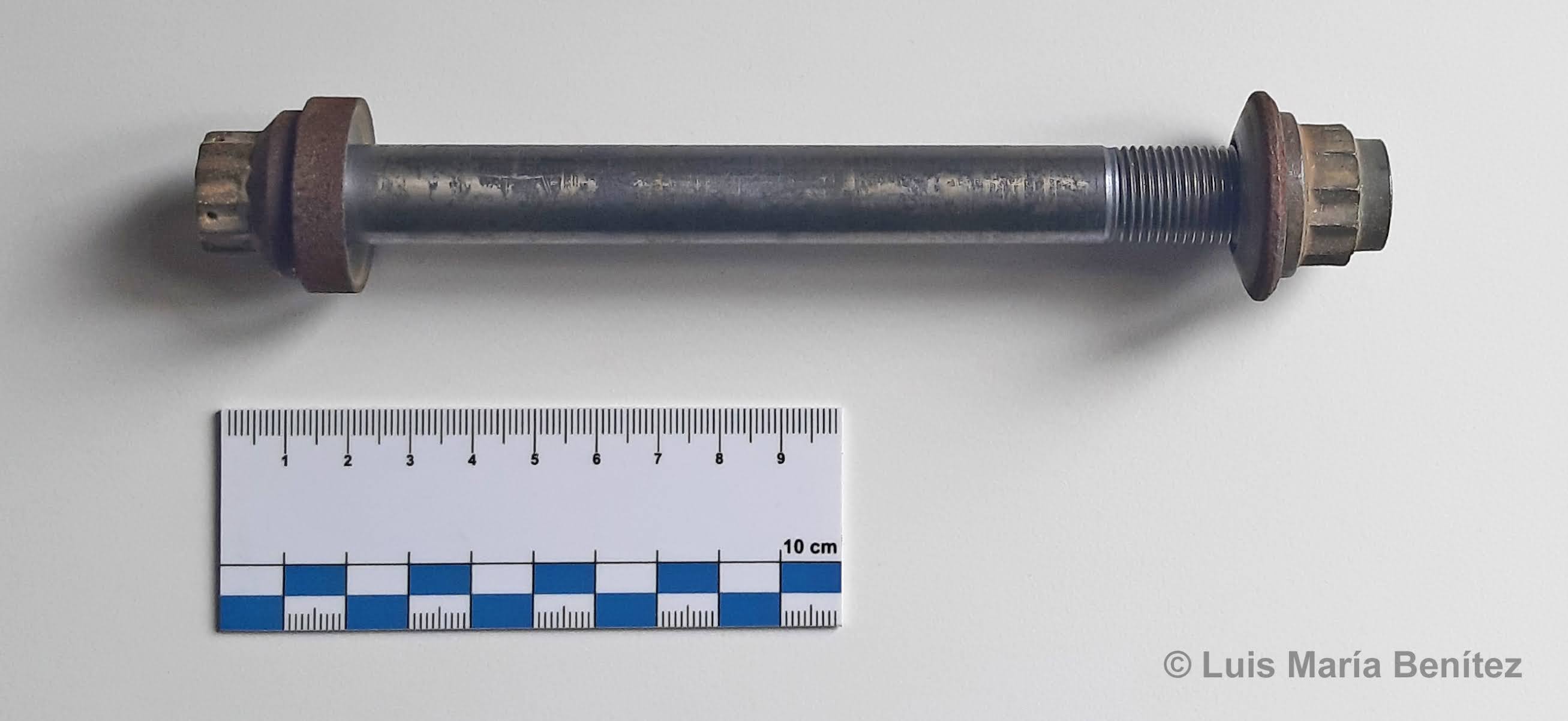
Size: 18.5 x 3.4 cm. Weight: 371 gr. Part number: RD111-4016-1092. Manufacturer: Rocketdyne. Description: Used on the F-1 engine of Sat...
Apollo F1 LOX turbopump volute flange bolt
November 29, 2021
Item: Saturn V Instrument Unit Mylar Thermal Radiation Shroud.
Size: 6.6 x 8.6 cm. Attachment cords: 38.8 cm.
Manufacturer: IBM
Description:
Item: Saturn V Instrument Unit Mylar Thermal Radiation Shroud. Size: 6.6 x 8.6 cm. Attachment cords: 38.8 cm. Manufacturer: IBM Descrip...
Apollo Saturn V Instrument Unit Mylar Thermal Radiation Shroud
Size: 6.6 x 8.6 cm. Attachment cords: 38.8 cm.
Manufacturer: IBM
Description:
The Instrument Unit (I.U.) was the "brains" or control center of the Saturn Heavy Launch Carrier Vehicle. An Environmental Control System was used in the I.U. to provide cooling for electronic modules and components within the I.U. and forward compartments of the third stage.
Credit: NASA.
This artifact is part of a Thermal Radiation Shroud that was used to improve the Environmental Control System's heat balance, by covering the inboard surfaces of the Thermal Conditioning Panels and Components. They are attached to the Cable Tray at the top, to the Cable Tray supports at the sides, and to the coolant return manifolds at the bottom. Air/GN 2 purge gas from the Environmental Conditioning Duct is vented through open areas at the top and bottom of the shrouds and through holes in the shrouds.
Credit: NASA.
Credit: IBM.
The shrouds are fabricated from sheets of aluminized, low-thermal-emissivity mylar and bound with aluminum tape. The tape is used to reinforce the shrouds at the edges and around the vent holes. The shrouds are installed at KSC in the required locations for each vehicle effectivity.
In those locations where RF interference would result from the use of a shroud type shield, a low-emissivity, pressure-sensitive tape is used. The tape is applied to accessible exposed surface areas of components and / or Thermal Conditioning Panels.
Subscribe to:
Comments (Atom)


Follow me